Busbars are at the core of every modern, high-current power distribution architecture, and for engineering teams across the UAE and GCC, they are now a strategic design choice rather than just an alternative to wiring. When specified and engineered correctly, advanced busbar systems such as ROLINX laminated busbars enable higher power density, lower losses, better thermal behaviour, and simpler integration across aerospace, EV, renewable energy, and industrial applications.
What are busbars and why do they matter?
Busbars are rigid conductors, typically made from copper or aluminium, that distribute electrical power to multiple circuits or devices through a central, low‑impedance pathway. Instead of running many separate cables, engineers use a busbar system as a shared backbone, improving current‑carrying capacity, wiring organisation, and system reliability in compact, high‑power designs.
In high‑demand environments—such as EV powertrains, renewable energy inverters, industrial drives, and aerospace converters—busbars help to:
- Support very high currents while maintaining an acceptable temperature rise.
- Minimise parasitic inductance, improving switching behaviour in power electronics.
- Simplify assembly and maintenance by replacing large cable bundles with structured, engineered conductors.
These advantages explain why busbar solutions are now a default choice in many medium‑ and high‑power platforms, especially where space, efficiency, and reliability are critical design constraints.
Copper, aluminium, and surface finishes in busbars
The performance of any busbar connector or laminated structure is strongly influenced by conductor material and surface treatment. Copper busbars are widely used thanks to their very high conductivity and excellent thermal properties, while aluminium offers a lighter and more cost‑effective option for specific current densities when designed properly.
Typical engineering choices include:
- Copper busbars for maximum conductivity, lower resistance, and improved thermal performance, suitable for compact, high‑power converters and drives.
- Aluminium busbars where weight and cost per unit length are important, with carefully engineered cross‑sections and joints to compensate for lower conductivity.
- Surface plating (such as tin, nickel, or silver) applied to contact areas to reduce oxidation, improve contact resistance, and maintain stable performance over time.
The final selection depends on current levels, allowable temperature rise, mechanical constraints, environmental conditions, and total cost targets for the busbar system.
Key technical benefits of using busbars
Engineers increasingly choose busbars over cables because they deliver measurable gains in performance and total cost of ownership. When well designed, a laminated busbar solution brings several key benefits to power distribution networks.
- Space optimisation: Flat, layered conductors can be stacked and shaped to fit within tight envelopes, often reducing required installation volume compared to multi‑cable bundles.
- Thermal performance: The high surface‑area‑to‑volume ratio supports efficient heat dissipation, which helps keep operating temperatures under control and extends component lifetime.
- Electrical efficiency: Optimised cross‑sections and short current paths reduce resistance and stray inductance, lowering I²R losses and improving converter efficiency and transient behaviour.
- Safety and reliability: Rigid, encapsulated designs minimise the risk of abrasion, loose strands, or inconsistent routing, reducing fault risk and improving long‑term reliability.
- Installation and maintenance: Modular busbar assemblies are quicker to install, easier to reproduce, and simpler to modify during upgrades or expansions than complex cable harnesses.
These combined advantages make busbars an attractive choice wherever high power, tight packaging, and repeatable quality are required.
Why laminated busbars outperform traditional busbars and cables
Traditional solid busbars offer clear benefits over cables, but laminated busbars take performance and integration to another level by stacking conductive layers separated by insulation. This geometry creates a tightly coupled structure with very low loop inductance and controlled parasitics, ideal for fast‑switching power electronics.
In practice, laminated busbar solutions provide:
- Lower inductance thanks to closely spaced, opposing current paths, leading to reduced voltage overshoot and better EMI behaviour in converters and inverters.
- Higher power density by combining multiple layers in a compact form while maintaining safe clearances and creepage distances.
- Improved EMC performance because controlled geometry and multi‑layer stacking help minimise radiated and conducted emissions.
Compared with cable‑based wiring, laminated structures also deliver better repeatability, simplified routing, and improved mechanical robustness against vibration and thermal cycling.
ROLINX laminated busbar families and their roles
Global brands such as ROLINX (Rogers) have developed a broad portfolio of laminated busbar families tailored to different voltage ranges, current levels, and environmental conditions. Each family targets a specific set of performance and cost requirements, allowing designers to match the busbar system precisely to application needs.
Typical ROLINX busbar families include:
- Performance‑oriented laminated busbars for medium and high voltage systems requiring optimised inductance and partial discharge control.
- Thermally enhanced variants capable of operating at higher temperatures, supporting applications with demanding thermal cycles or limited cooling capacity.
- Hybrid busbars integrating both power and signal paths into a single structure for applications such as EV battery modules and compact powertrains.
- Compact and housing‑integrated solutions where the busbar is combined with mechanical housings or insulation systems to save space and simplify assembly.
The diversity of the ROLINX range allows engineers across aerospace, EV, industrial drives, and renewable energy to standardise on a trusted platform while tailoring geometry, materials, and interfaces per project.
Electrical design parameters: current, voltage, clearance, and creepage
Designing a safe, robust busbar system requires careful attention to current, voltage, and insulation parameters, especially in high‑reliability markets like aerospace and rail. For any laminated busbar, engineers must specify:
- Current rating and cross‑section so that the conductor can carry the required load with acceptable temperature rise under worst‑case operating conditions.
- Voltage levels and insulation system, including rated insulation voltage, impulse withstand capability, and test voltages defined by relevant standards.
- Clearance and creepage distances based on pollution degree, overvoltage category, and insulation material group, ensuring adequate insulation in real operating environments.
In sectors such as traction, aerospace, and HV power conversion, compliance with standards like EN 50124 for insulation coordination and IEC frameworks for testing is a baseline requirement rather than an option.
Thermal performance and environmental limits
Thermal management is central to busbar design because resistive heating and ambient conditions can quickly push conductors and insulation beyond safe limits. ROLINX and similar laminated busbar systems are engineered with specific operating and storage temperature ranges, as well as guidelines for humidity and cooling conditions.
Typical considerations include:
- Continuous operating temperature range, often extending from very low sub‑zero conditions up to elevated values suitable for power electronics cabinets and traction systems.
- Storage and transport ranges to ensure mechanical and insulation stability even when equipment is stored in harsh climates.
- Cooling assumptions, such as natural convection or forced air, that must be matched with enclosure and system‑level thermal design.
By combining accurate thermal modelling with testing, busbar suppliers help customers validate that laminated structures will remain within safe temperature margins under real‑world load profiles.
Mechanical design: geometry, bending, and mounting
From a mechanical perspective, busbars must be robust enough to handle installation, vibration, and thermal cycling without cracking or delamination. Minimum bend radii, thickness selection, and mounting strategies all contribute to long‑term reliability.
Key mechanical aspects include:
- Bending guidelines that define minimum radii as a function of conductor thickness and insulation, to prevent mechanical stress concentrations and damage.
- Thickness and layer count optimised for both current capacity and mechanical stiffness, balancing rigidity with the need for some flexibility during assembly.
- Mounting and support using appropriately placed fasteners, spacers, and housings to distribute loads and limit vibration.
In applications with high vibration, such as transportation and aerospace, these mechanical details are extremely important to ensure that the busbar system maintains electrical integrity throughout its service life.
Connection technologies and interface options
The way a busbar connects to the rest of the system has a direct impact on resistance, heat generation, and maintainability. ROLINX and similar platforms support a variety of termination techniques and interface geometries designed to simplify system integration and keep contact resistance low.
Common connection methods include:
- Bolted joints with optimised washer and bushing designs to ensure even pressure distribution and reliable long‑term contact.
- Integrated connectors for plug‑and‑play interfaces, especially in modular battery systems and power modules.
- Soldered or welded terminations where extremely low resistance and compact packaging are critical.
Careful selection of plating, surface roughness, and fastening hardware helps to minimise micro‑movement, fretting corrosion, and hot spots over the lifetime of the system.
Typical applications of ROLINX busbar systems
Advanced laminated busbars have become a preferred solution in multiple sectors where high power, high reliability, and compact form factors are required. ROLINX busbar systems are particularly relevant in:
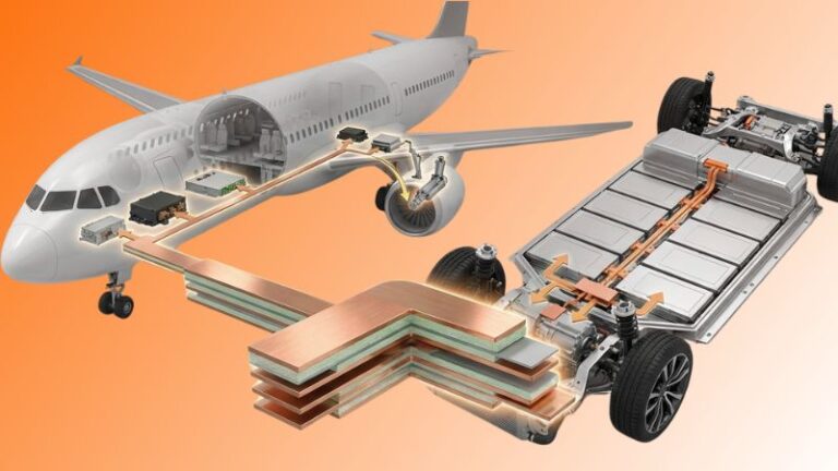
- Electric and hybrid vehicles, where they connect battery cells, inverters, DC‑link capacitors, and motor drives in compact, high‑current architectures.
- Renewable energy systems, including solar inverters and wind turbine converters, where improved efficiency and reliable power handling directly influence energy yield.
- Rail and industrial drives, where long lifetimes, high currents, and demanding environmental conditions require robust, low‑inductance power distribution.
- Aerospace and e‑aviation, where laminated busbars support compact power electronics, more‑electric aircraft systems, and high‑altitude operating conditions.
In each of these sectors, busbar solutions are not just replacements for cables; they become an integral design element that shapes overall performance, packaging, and serviceability.
Engineering and simulation support for critical busbar projects
Complex projects benefit from more than just hardware; they require engineering support, simulation tools, and testing capabilities to ensure that the chosen busbar architecture meets all electrical, thermal, and mechanical targets. Leading suppliers therefore offer:
- Current, heating, and inductance simulations to optimise conductor geometry and layer arrangements before committing to tooling.
- Electrical test programmes including high‑potential tests, partial discharge measurements, and endurance cycles to validate insulation performance.
- Mechanical and environmental testing, such as thermal cycling and vibration, to confirm long‑term reliability under application‑specific conditions.
This engineering collaboration helps reduce design risk, control development costs, and shorten time to market for high‑power platforms using busbar architectures.
Optimise your next power platform with busbar solutions
If your next project involves high‑current power distribution—whether in EVs, renewable energy, industrial drives, or aerospace systems—this is the right moment to consider an engineered busbar system instead of incremental cable upgrades. By adopting ROLINX or similar laminated busbar solutions, engineering teams can unlock higher efficiency, better thermal margins, and cleaner layouts while improving reliability and easing maintenance.